


|
Multilin 489 - Legacy
Generator Protection System
Manufacturing for 489 has been discontinued. As an alternative, please refer to the 889 relay. The SR489 Generator Protection System, a member of the SR family of relays, provides protection, control and advanced communications in a cost effective industry leading draw-out construction. Designed for small and medium sized generators, the 489 delivers advanced protection including generator stator differential protection. The 489 also includes detailed diagnostic information allowing for reduced troubleshooting time. Key Benefits
Key Benefits
|
Key Features
Protection & Control
The 489 Generator Protection System provides comprehensive protection, metering, and monitoring of small to medium sized synchronous or induction generators operating at 25, 50 or 60 Hz. The 489 is ideally suited for primary or backup generator protection as well as for use in cogeneration applications. Protection features found in the 489 include:
Key Features
Monitoring & Control
 Analyze generator faults using waveforms that are captured at the time of generator faults or system instabilities
Advanced Automation
The 489 offers a multitude of different analog and digital inputs and outputs to allow the 489 to be seamlessly integrated into most generator automation schemes.
Outputs Relays
The 489 provides six output contacts for the purpose of controlling or signaling other devices and operations personnel. Protection elements can be configured to control the Trip contact, the Alarm contact, or the 3 Auxiliary contacts whenever the element operates. The status of each of these contact are also displayed on LEDs found on the relays front panel.
Digital Inputs
Eight digital inputs are available for monitoring the status of external contacts, tachometers, or control switches. With these inputs, the relay can identify the status of the associated breakers and receive commands from operational staff such as controlling the output relays, resetting the thermal limits, or triggering a waveform capture.
RTD Inputs
Twelve RTD inputs allow the 489 to monitor both the generator stator and bearing temperature. A built in voting feature adds additional security by ensuring that two RTDs monitoring the same device both detect the overtemperature condition before tripping the generator offline.
Analog Inputs
Four analog inputs are available for providing protection and monitoring of generator bearing vibration. The analog inputs are field programmable to measure transducer signals that operator over a range of 0 to 1 mA, 0 to 20 mA, or 4 to 20 mA.
Analog Outputs
Four analog outputs are available for signaling the value of measured analog quantities to external process control devices such as PLCs. The analog outputs can be ordered to operate over a 4 to 20mA range or a 0 to 1mA range and can be configured to signal a representation of most analog quantities measured by the 489 including currents, voltages, frequency.
Key Features
Advanced Communications
The 489 provides advanced communications technologies for remote data and engineering access, making it easy and flexible to use and integrate into new or existing monitoring and control systems. Multiple communication ports are available including a front panel RS232 serial port for easy local computer access, two RS485 serial ports and a 10Mbps copper Ethernet port that provide direct integration in most communications architectures.
The 489 supports the most popular industry standard protocols enabling easy, direct integration into most DCS and SCADA systems. Protocols supported include:
Front Panel
Rear Connections
EnerVista™ Software
The EnerVista™ Suite is an industry-leading set of software programs that simplify every aspect of using the 489 relay. The EnerVista™ suite provides all the tools to monitor the status of your protected asset, maintain the relay and integrate information measured by the 489 into DCS or SCADA monitoring systems. Convenient COMTRADE and Sequence of Events viewers are an integral part of the 489 Setup software included with every relay to carry out postmortem event analysis. Learn More
8 Series Retrofit Kit
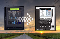
Explore the 8 Series Retrofit Kit
Retrofit Existing SR 489 Devices to the Multilin 889 in Minutes
Traditionally, retrofitting an existing relay has been a challenging, time consuming task often requiring re-engineering, new drawings, panel modifications, re-wiring and re-testing.
The 8 Series Retrofit Kit provides a quick, 3-step solution to upgrade previously installed SR 489 relays. With the new 8 Series Retrofit Kit users are able to install the 889 Generator Management System without modifying existing cutouts and wiring, and without any drawing changes or re-engineering time.
Easy 3-Step Process to Upgrade in as Fast as 21 Minutes
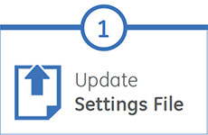
EnerVista 8 Series Setup Software provides automated setting file conversion. Once completed, a graphical report is provided to verify and call out any specific settings that may need attention. |
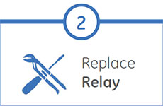
Simply remove the upper, lower and low voltage terminal blocks and then remove the SR chassis from the panel. No need to disconnect any of the field wiring. |
Insert the new 8 Series Retrofit chassis into the switchgear and simply plug-in the old terminal blocks - there is no need to make any cut-out modifications or push and pull cables. |


