


|
Multilin 869
Comprehensive Motor Protection and Management
The Multilin 869 relay is a member of the Multilin 8 Series protective relay platform and has been designed for the protection, control and management of medium and large induction and synchronous motors. The 869 is equipped with an integrated synchronous motor protection module for protection and control of synchronous motors. The Multilin 869 provides advanced functionality for various types of applications such as high-speed protection, extensively customizable programmable logic, advanced motor monitoring and diagnostics, and flexible configuration capabilities. Advanced communications of the 8 Series platform allows easy integration into process and electrical control systems for smoother asset monitoring and control. To simplify the migration and upgrade from an existing SR 469 protection relays, retrofit have been developed which significantly simplify the upgrade process. Learn more |
Enhanced Motor Protection functions (FW2.4)
Single Unit-based Solution for Protection, Control & Monitoring of Sync. and Induction Motors
Starting Control
Squirrel Cage Rotor Thermal Protection (separate from the main thermal model)
Enhanced Thermal Protection with Speed Biasing
Enhanced power factor protection
Power Factor Based Regulation
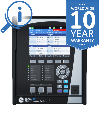
Full Color Graphical HMI Front Display
A large, full color Graphic Control Panel (GCP) ensures clear representation of critical status and measurements. The 8 Series offers two options for front panels:
Switchgear Control and Configurable SLD
The Multilin 8 Series provides a configurable dynamic SLD up to six (6) pages for comprehensive switchgear control of up to 3 breakers and 9 disconnect switches; including interlocks. Up to 15 digital and metering status elements can be configured per SLD page.
Multilin 869 Overview
The Multilin 869 Motor Protection System is a protection device designed for the management, protection and control of medium to large horsepower motors. The 869 provides comprehensive protection and control of various types of motors with different loads they run.
With a fast protection pass, running every 1/8th of a cycle, the 869 relay provides faster current, voltage, power and frequency protection elements ; helping reduce stress on assets. The Multilin 869 supports the latest standard communication protocols, including IEC 62439/PRP and IEC 61850 Ed2 ; facilitating easy integration into new or existing SCADA/DCS networks.
Key Benefits
Applications
Multilin 869 motor protection relay functional block diagram
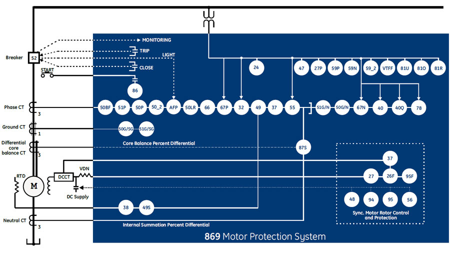
ANSI Device Numbers & Functions
|
|
|
High-Inertia Load Applications
The voltage dependent overload curve feature in Thermal Model is tailored to protect motors which are used in high inertia load applications. Voltage is continually monitored when the motor is started and during acceleration. The thermal limit curve is then adjusted accordingly. This enables the Multilin 869 to distinguish between a locked rotor condition, an accelerating condition and a running condition.
VFD-Driven Motor Applications
The Multilin 869 provides protection for motors fed through VFDs (Variable Frequency Drives). A wide range of the frequency tracking (3-72Hz) allows the 869 to track the motor frequency and adjust its sampling rate to accurately measure phasors. An advanced algorithm allows switchable current and voltage tracking in case VFD is bypassed.
Thermal protection also considers the extra heating generated by the higher harmonics due to VFD to achieve the accurate response to the actual motor heating. RMS currents fed to the various motor protection elements are further processed through the averaging filter to eliminate oscillations in current signals to ensure the security.
Additionally, users may indicate a starting VFD frequency that helps the device to track the motor frequency faster and therefore accurately measures the phasor quantities, which, otherwise, could cause delayed or false protection operation of the protection.
Cyclic Load Motor Applications
Input currents of a motor driving cyclic load can vary between very low to above the maximum allowable current during a load cycle. Variation in current magnitude results in motor heating and cooling depending on the heat and cooling time constants. Thermal overload protection response is made adaptive to the cyclic load based on the cooling time constants. In addition, to provide more accurate overload thermal model response to cyclic load, the input currents to the thermal model are averaged over the settable duty cycle interval. With a reciprocating load application, the number of cycles to average can be determined from current waveform capture using the Oscillography/Datalogger features in the GE motor protection relays
Synchronous Motor Applications
869 provides functions essential to protect the synchronous motor during asynchronous operation while startup, during normal and overload operations and under fault conditions. In addition to stator protection and control, it provides protection and monitoring of exciting rotor during pull-out or loss of synchronism condition with elements like Out-of-Step, Loss-of-Field, Reactive Power, and Power Factor. With its well established and matured Thermal Model, it prevents overheating of both stator and rotor windings during both synchronous and asynchronous operation. During asynchronous operation or startup, the thermal model with VD (voltage dependent) function provides protection against excessive heating in the damper winding due to stalled or locked rotor conditions.
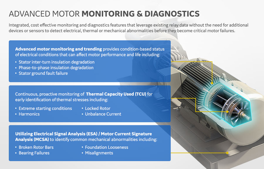
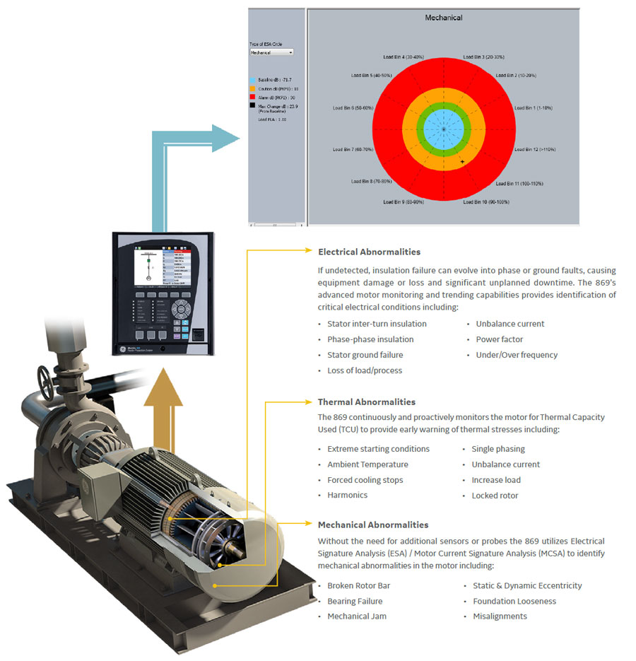
Advanced Motor Monitoring & Diagnostics
The Multilin 869 offers an integrated, cost effective Monitoring and Diagnostics features that leveraging existing relay data without the need for additional devices, sensors, wiring or training.
Watch our Tech Talk: Electrical Signature Analysis for a Real-Time Motor Condition Monitoring System
Environmental Monitoring
The 869 implements a patented environmental monitoring system that measures and provides operating condition information. Reliable and secure operation of the 869 relay and other electronic devices in the vicinity may be affected by environmental factors. The 869 relay has been designed to meet or exceed all required industry standards. Some operating conditions may be beyond those standards and reduce total lifespan of the device.
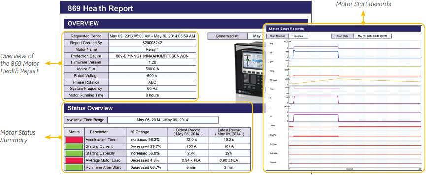
Multilin 869 Motor Health Report
Integrated Arc Flash Protection
The Multilin 8 Series supports an integrated arc flash module providing constant monitoring of an arc flash condition within the switchgear, motor control control centers, or panelboards. With a 2ms protection pass, the 8 Series is able to detect light and overcurrent using 4 arc sensors connected to the 8 Series relay. In situations where an arc flash/fault does occur, the relay is able to quickly identify the fault and issue a trip command to the associated breaker thereby reducing the total incident energy and minimizing resulting equipment damage.
Self-monitoring and diagnostics of the sensors ensures the health of the sensors as well as the full length fiber cables. LEDs on the front panel display of the 869 can be configured to indicate the health of the sensors and its connections to the relay.
Fast, reliable arc flash protection with light-based arc flash sensors integrated within the Multilin 8 Series of protection & control devices. With arc flash detection in as fast as 2msec, the costs associated with equipment damage and unplanned downtime is significantly reduced.
Communications
The 869 provides advanced communications technologies for remote data and engineering access, making it easy and flexible to use and integrate into new and existing infrastructures. Direct support for fiber optic Ethernet provide s high-bandwidth communications, allowing for low-latency controls and high-speed file transfers of relay fault and event record information. The 869 also supports two independent IP addresses, providing high flexibility for the most challenging of communication networks.
Providing several Ethernet and serial port options, dual independent Ethernet Ports, and support for a wide range of industry standard protocols, the 869 enables easy, direct integration into DCS and SCADA systems. The 869 supports the following protocols:
The 869 has two interfaces as USB front port and Wi-Fi for ease of access to the relay. Wi-Fi Connectivity:
Cyber Security
The 869 cyber security enables the device to deliver full cyber security features that help operators to comply with NERC CIP guidelines and regulations.
AAA Server Support (Radius/LDAP)
Enables integration with centrally managed authentication and accounting of all user activities and uses modern industry best practices and standards that meet and exceed NERC CIP requirements for authentication and password management.
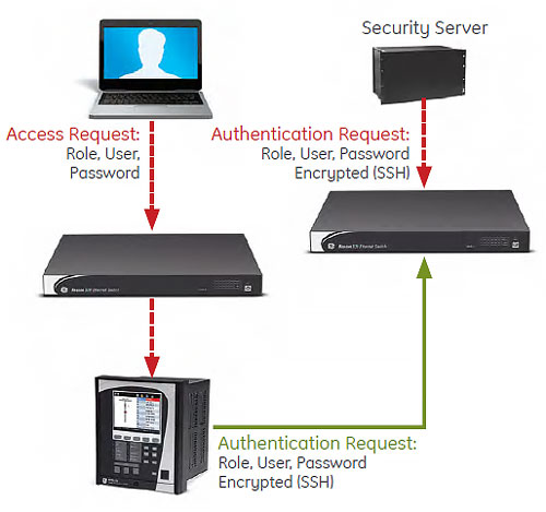
Role Based Access Control (RBAC)
Efficiently administrate users and roles within UR devices. The new and advanced access functions allow users to configure up to five roles for up to eight configurable users with independent passwords. The standard “Remote Authentication Dial In User Service” (Radius) is used for authentication.
Event Recorder (Syslog for SEM)
Capture all cyber security related events within a SOE element (login, logout, invalid password attempts, remote/local access, user in session, settings change, FW update, etc), and then serve and classify data by security level using standard Syslog data format. This will enable integration with established SEM (Security Event Management) systems.
Software & Configuration
The EnerVista™ suite is an industry-leading set of software programs that simplifies every aspect of using the Multilin 869.
EnerVista provides all the tools to monitor the status of the protected asset, maintain the device and integrate the information measured by the Multilin 8 Series, into SCADA or DCS process control systems. The ability to easily view sequence of events is an integral part of the setup software, as postmortem event analysis is critical to proper system management.
EnerVista Launchpad
The setup tools within Launchpad allow for the configuration of devices in real-time, by communicating via serial, Ethernet or modem connections, or offline by creating device setting files to be sent to devices at a later time.
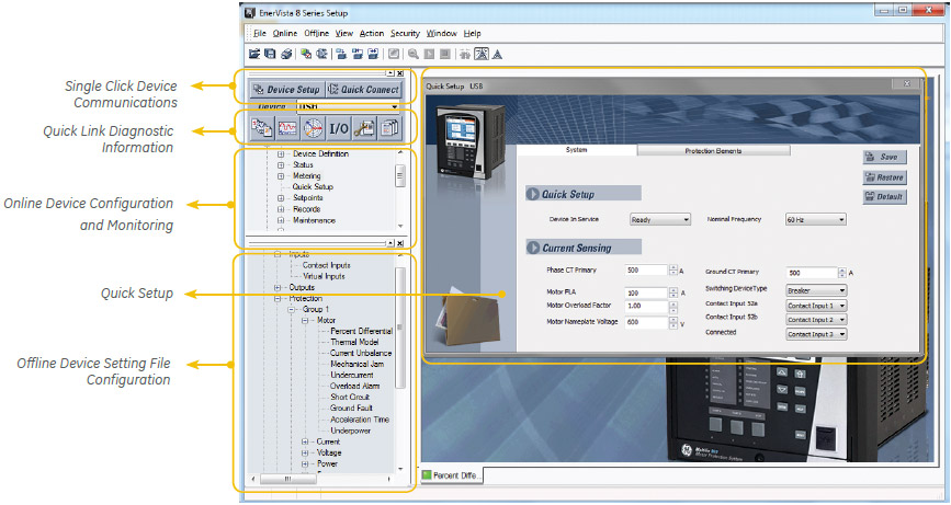
8 Series Setup Software
8 Series Setup Software is single setup and configuration tool across the platform and can reduce device setup and configuration time.
Simplified Setup & On-Going Maintenance
8 Series Retrofit
Explore the 8 Series Retrofit
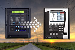
Retrofit Existing SR 469 Devices to the Multilin 869 in Minutes
Traditionally, retrofitting an existing relay has been a challenging, time consuming task often requiring re-engineering, new drawings, panel modifications, re-wiring and re-testing.
The 8 Series Retrofit provides a quick, 3-step solution to upgrade previously installed SR 469 relays. With the new 8 Series Retrofit users are able to install the 869 Motor Protection System without modifying existing cutouts and wiring, and without any drawing changes or re-engineering time.
Easy 3-Step Process to Upgrade in as Fast as 21 Minutes
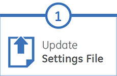
EnerVista 8 Series Setup Software provides automated setting file conversion. Once completed, a graphical report is provided to verify and call out any specific settings that may need attention. |
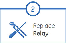
Simply remove the upper, lower and low voltage terminal blocks and then remove the SR chassis from the panel. No need to disconnect any of the field wiring. |
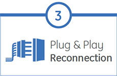
Insert the new 8 Series Retrofit chassis into the switchgear and simply plug-in the old terminal blocks - there is no need to make any cut-out modifications or push and pull cables. |